for Ergonomics, Biomechanics & Medicine

DataLOG Key Features
Management and Analysis Software
Optional Accessories
Specifications
DataLOG Minimum PC Requirements
More Biometrics Products
More Medical Products
Biometrics DataLOG
DataLOG is a fully portable subject worn programmable Data Acquisition Unit allowing the user to collect both analog and digital data from a wide range of sensors including Biometrics goniometers, torsiometers, EMG sensors, pinch meters, hand dynamometers, NexGen's whole body and hand-arm accelerometers, and Tekscan force sensors. Examples of other general sensor inputs include accelerometers, load cells, general strain gauges, potentiometers, temperature probes and flow meters.
The DataLOG can be synched to NexGen's I2M motion capture solution based on inertial sensors and its HM-Analyzer software. Typical configurations include synchronization with Biometrics' force plates and EMG sensors.
DataLOG Key Features
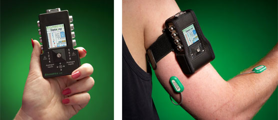
The NEW DataLOG MWX8 is the latest in data acquisition technology developed to meet the needs of researchers for portable data collection and ambulatory monitoring in human performance, sports science, medical research, industrial ergonomics, gait laboratories, & educational settings. You can time synchronize a single video file with the data collected. The small, lightweight, battery operated unit incorporates a colour graphics LCD, joystick, micro SD card interface, and a real-time wireless Bluetooth link to a PC.
Weighing 60% less than previous devices, at 129g, the DataLOG MWX8 can be worn on the arm or leg in addition to the traditional belt/waist placement. This miniaturized technology is by far the most powerful portable data acquisition device available. During all stages of the design and development process, attention has been given to the Bluetooth® Wireless link, providing real time data transfer and display. In addition, the data is automatically backed up to the Micro SD card providing complete peace of mind.
DataLOG is a general purpose, programmable Data Acquisition Unit allowing the user to collect both analogue and digital data from a wide range of sensors. All Biometrics Ltd sensors readily connect to the DataLOG including:
- Single and Twin Axis Goniometers
- Torsiometers
- Surface EMG
- Accelerometers
- Contact Switches & Event Markers
- ForcePlates
- MyoMeter
- Hand Dynamometers
- Pinchmeters
The front end amplifier configuration and sensor power supply are programmable enabling the researcher to also connect a wide range of general or custom transducers including:
- General Load cells
- Strain gauge devices
- Single ended voltage inputs
- Differential voltage inputs
- Temperature probes
- Flow meters
- Microphones
The DataLOG is configured from the host PC using the Bluetooth® wireless link, including simple adjustments per channel for gain, power supply, sampling rate and datum settings. When Biometrics' sensors are connected these parameters are automatically set using a drop down menu.
After configuring from the PC, many operations are carried out using the DataLOG LCD & menu system. The screens are selected by scrolling left or right using the navigation joystick.
Data recording options include:
- display and analyse real time within the PC using Bluetooth®
- store on the PC and auto-back-up to the Micro SD card
- store data to the Micro SD card for later download
- transfer data real time using the Dynamic Link Library into 3rd party programs using tools such as MS Visual Basic or Visual C++
- store as ASCII or as a standard Sound Wave file for passing into other applications such as Microsoft Excel or Cool Edit
- display real time on the DataLOG Graphics Display in engineering units, or as a bar chart, or as adjustable audible alarms
- manual start with pre-set automatic stop
- remote record start/stop by TTL signal sent from other instrumentation to the DataLOG
- start/stop other instrumentation by TTL signal sent from the DataLOG
Management and Analysis Software
The DataLOG uses a comprehensive program to configure the input parameters, upload the collected data, and analyse the results. The software also reads stored DataLINK files.
The DataLOG Display and Analysis Software may open an unlimited number of data files, and the time axis may be tracked across all files allowing display and analysis for a large number of channels.
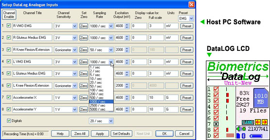
DataLOG Analog Inputs
The Channel Configuration window is used to set up way that data is converted into digital values and to program the operation parameters of the DataLOG for the intended application. The specific engineering units can be labelled on each channel.
Help Menu
Full operating instructions and technical information are in the online help.
DataLOG Digital Inputs
This dialogue controls the operation of the four digital inputs and the start/stop input.
Optional Accessories
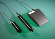
Event Markers
These useful accessories allow time marks to be registered in the recorded data. The events are marked for the duration of the time the switch is pressed:
- IS3 - A 1.8 meter cable with a suitable connector at one end to connect to the DataLOG, and a hand held switch at the other
- IS3LED - same as above with LED in the hand held switch which illuminates when the switch is pressed for visualization on video recordings
- IS3Pedal - A 2 meter cable with a suitable connector at one end to connect to the DataLOG, and a foot switch at the other. This allows events to be marked while leaving both hands free
Force Sensors
Individual Tekscan Flexiforce sensors can be connected using the TK1000 cable.
EMG Sensors
Up to 8 EMG sensors can be added (product # SX230). One R506 Ground (Earthing) strap (per system) is required when connecting EMG sensors. See also DataLINK/DataLOG EMG Sensors.
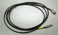
Synchronization Cable SYNC1
This cable is used for remote start/stop of the DataLOG by a signal (TTL) sent from other hardware systems to synchronize data collection. The SYNC1 is a 2 meter (approx 6') cable with a connector at one end to connect to the digital input socket of the DataLOG and 2 flying wires at the other end.
The start/stop input performs an action when the input changes from logic 0 to logic 1. When the 2 wires are switched closed circuit, the logic changes from 0 to 1 to activate unit start. When the 2 wires are again closed circuit, the logic changes again from 0 to 1 to activate the unit stop.
The cable may be ordered with the 2 flying wires or any connector may be specified.
Synchronization Cable SYNC1BNC
A synchronization cable with a BNC connector fitted for interfacing to 3rd party systems such as Qualisys, Vicon and other motion capture systems.
IS2 Remote Start/Stop Switch
The IS2 remote start/stop switch is a 1.8 meter cable with a suitable connector at one end to connect to the DataLOG, and a hand held switch at the other. Pressing the switch will activate the start or stop recording function.
IS4LED Remote Start/Stop for Video Synchronization
The IS4LED remote start/stop switch is a 1.8 meter cable with a suitable connector at one end to connect to the DataLOG, and a hand held switch at the other. Pressing the switch will activate the start or stop recording function which will then activate the LED, which can be seen in the video and used as a synchronization point.
IS5LED Record Indicator
The IS5LED is an indicator LED switch that illuminates when the DataLOG starts or stops recording data.
Synchronization Cable SYNC5
For remote start/stop by a TTL signal sent to 3rd party hardware systems to synchronize data collection from both sources (i.e. DataLOG is the master). The SYNC5 is a 3 meter cable with a connector at one end to connect to the digital input socket of the DataLOG and 2 flying wires at the other end. Alternatively, this cable may be specified with any connector of choice.
Synchronization Cable SL100
Synchronization cable SL100 is used to synch two or three MWX8 DataLOG units. One SL100 is required to synch two DataLOGs, two SL100s are required for 3 DataLOGs.
Cables
| Type Number | Length (mm) | Description |
| D1500 | 1500 | Connection of general sensors to DataLOG |
| J500 | 500 | Connection of Goniometers and Torsiometers to DataLOG |
| J1000 | 1000 | Connection of Goniometers and Torsiometers to DataLOG |
| J1500 | 1500 | Connection of Goniometers and Torsiometers to DataLOG |
| SYNC1 | 2000 | Remote start/stop synchronisation cable |
| H2000 | 2000 | Connection of Biometrics' MyoMeter, Dynamometer, Pinchmeter or ForcePlates ( FP3 / FP4 ) to DataLOG |
Specifications (DataLOG Model MWX8)
Dimensions: 104 x 62 x 22 mm
Mass: 129 g
Battery type: 2 x Alkaline AA, LR6, MN1500
Battery life: 5-11 hours nominal depending on sensor type & quantity
Microprocessor controlled programmable gain amplifiers
Analog channels: 8
Digital channels: 4
Memory Internal: 2GB Micro SD card
Bluetooth® Adaptor: Microsoft Bluetooth® stack compatible
Front end ADC: 14 bit giving ± 4000 counts resolution
Number of goniometer channels: 0 to 8, dependent on number of general analog channels (user select)
Number of general analog channels: 0 to 8, dependent on number of goniometer channels (user select)
General analog channels may be single ended or differential dependent on front end plug wiring configuration
Hardware Gain range options
| Max Input | Resolution |
| ±1 mV | 0.244 µV |
| ±3 mV | 0.732 µV |
| ±10 mV | 2.44 µV |
| ±30 mV | 7.32 µV |
| ±100 mV | 24.4 µV |
| ±300 mV | 73.2 µV |
| ±1 V | 0.244 mV |
| ±3 V | 0.732 mV |
| ±6 V | 1.464 mV |
Recording modes: record to Bluetooth® & Micro SD card, record to Micro SD card only,
record to Bluetooth® only
Range of Sampling frequency per analog channel: 1, 2, 5, 10, 20, 50, 100, 200, 500, 1000, 1250, 2000, 2500, 5000, 10000, 20000 Hz (Note: Bluetooth is used for monitoring only at the higher sampling rates)
Bandwidth:
Input Range 1mV and 3mV, Bandwidth DC to 1KHz (+0 dB / -3dB)
Input Range 10mV to 3V, Bandwidth DC to 10KHz (+0 dB / -3dB)
an automatic anti-alias digital filter: approximately -3dB at 0.45 x sampling rate and a maximum attenuation of -13dB above 0.8 x sampling rate
Power supply per channel: adjustable 0 to 4.6 Vdc
Current supply per channel: ≤20 mA
Accuracy: better than ± 0.5% full scale
Maximum common mode: 1.2 V
DataLOG Minimum PC Requirements
- OPERATING SYSTEM: Microsoft Windows 8 Home Premium or Professional, Windows 10 Home or Professional
- CPU: 32bit Processor (x86), running at 2GHz or Higher
- RAM: 2 GB or Higher
- GRAPHICS: Windows compatible dedicated video card with 1Gb min. vRAM
- DISPLAY: SVGA Monitor / Screen (1024 x 768 Pixels)
- SOUND: Windows compatible sound card
- OPTICAL DRIVE: Windows compatible CD-Rom / DVD-Rom
- HARD DRIVE: 20Mb free disk space for installation. Save Files will require more space.
- INPUT: 100% Windows compatible mouse / pointing device and keyboard
- CONNECTIVITY: 1 free USB 2.0 Port for the Microsoft Bluetooth Stack compatible Bluetooth Adapter Class 1 V2+EDR
- MicroSD Card Reader