for Ergonomics, Biomechanics & Medicine

DataLINK Management Software
Optional Accessories
Specifications
DataLINK Minimum PC Requirements
More Biometrics Products
More Medical Products
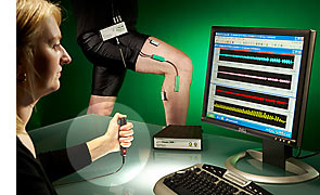
Biometrics DataLINK
DataLINK is a general purpose, subject-worn, programmable Data Acquisition System allowing the user to collect both analogue and digital data from a wide range of sensors including Biometrics' goniometers, torsiometers, EMG sensors, pinchmeters, hand dynamometers, NexGen's whole body and hand-arm accelerometers, and Tekscan force sensors. Examples of other general sensor inputs include load cells, accelerometers, general strain gauges, potentiometers, temperature probes and flow meters.
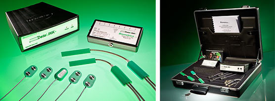
 The sensors connect to a small, lightweight Subject Unit with digital instrumentation amplifiers and programmable power supply responsible for energizing the sensors, sampling and converting the inputs into a digital output. The data is transferred from the Subject Unit to the tabletop Base Unit via a RS422 data transfer cable. This cable (type no. R7000) is usually 7 meters in length but may be specified any length up to 500 meters. The Base Unit connects to the PC via a USB cable where the data may be readily stored on disk as ASCII or passed real time into other applications such as Microsoft Excel or Microsoft Visual Basic using the DLL (dynamic link library). Analogue outputs may be obtained using the optional output cable type no. R2000I.
Each DataLINK unit comes with 8 analogue inputs, accommodating both single ended voltage inputs and differential voltage inputs. DataLINK also includes 5 digital inputs and the DataLINK Management Software. Configurations of 16 and 24 channels can be ordered with data synchronization. The DataLINK hardware is primarily digital circuitry, producing a design with the greatest accuracy, negligible drift, and the greatest immunity to noise.
You can time synchronize a single video file with the data collected.
Each input channel is individually configured and controlled within the versatile and easy to use DataLINK Management Software. Options for the analogue inputs include selectable gain, selectable sampling frequency, selectable sensor supply voltage, and selectable zero or datum position. Options for the digital inputs include selectable threshold level and selectable hysterisis level.
DataLINK Management Software
The DataLINK uses a comprehensive program to configure the input parameters, store the data or transfer it to other applications, and analyse the results. The software also reads stored DataLOG files.
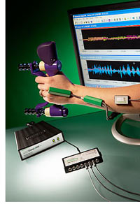
Main Data Display
The main data display window provides a real-time display of the data received from the DataLINK hardware.
DataLINK Channel Configuration window
To optimize the operation of the DataLINK for the intended application, the Channel Configuration window is used to set up the way the analogue data is converted into digital values.
Help Menu
Comprehensive online Help contains full operating instructions and technical support information.
DataLINK Digital Inputs window
The Digital Inputs window is used to match the digital inputs to the characteristics of the digital devices connected to them.
Optional Accessories
Ident Switch IS2
A 1.8 meter cable with a suitable connector at one end to connect to the DataLINK Subject Unit, and a hand held switch at the other. This useful accessory allows time marks to be superimposed on the recorded data enabling the operator to highlight specific events during data collection. The mark is shown in the software as a full scale spike across all channels of data.
Cables
| Type | Length (mm) | Description |
| D1500 | 1500 | Connection of general sensors to DataLINK |
| J500 | 500 | Connection of Goniometers & Torsiometers to DataLINK |
| J1000 | 1000 | Connection of Goniometers & Torsiometers to DataLINK |
| J1500 | 1500 | Connection of Goniometers & Torsiometers to DataLINK |
| R7000 | 7000 | RS422 cable from Subject Unit to Base Unit |
| R2000I | 2000 | Optional analogue and digital output cable |
| H1800 | 1800 | Connection of Pinchmeter & Dynamometer to DataLINK |
Specifications (DataLINK Model DLK900)
Mechanical
Subject Unit Dimensions: 130 x 65 x 25 mm
Subject Unit Mass: 200g
Base Unit Dimensions:173 x 154 x 60 mm
Base Unit Mass: 360g
Electrical
Analogue channels: 8 per unit
Digital channels: 5 per unit
Mains powered rated continuous
Microprocessor controlled programmable gain amplifiers
Front end ADC: 13 bit giving +/- 4000 counts
Communication with host PC: USB
Communication from Subject unit to Base unit: RS 422
General analogue channels may be single ended or differential dependent on the front end plug wiring configuration.
Hardware Gain range options:
| Gain | Max Input | Resolution |
| x 1000 | 1 mV | 0.244 mV |
| x 300 | 3 mV | 0.732 mV |
| x 100 | 10 mV | 2.44 mV |
| x 30 | 30 mV | 7.32 mV |
| x 10 | 100 mV | 24.4 mV |
| x 3 | 300 mV | 73.2 mV |
| x 1 | 1 V | 0.244 mV |
| x 0.3 | 3 V | 0.732 mV |
Range of sampling frequency per analogue channel: 10, 20, 50, 100, 200, 500, 1000, 2000, 5000 Hz (maximum 40,000 Hz sequential)
Sampling frequency digital channels: 100 Hz
Power supply per channel: 0 to 4,950 mV dc
Current supply per channel: <20 mA
Accuracy: better than ± 0.25 % full scale
Data interface: RS232 to host PC and analogue output via DACs contained in base unit
Analogue Output Sensitivity:
| Count Equivalent | Analogue Output | Goniometer Angle Equivalent |
| + 4000 | +4.5 Vdc | +180° |
| 0 | +2.5 Vdc | 0° |
| -4000 | +0.5 Vdc | -180° |
DataLINK Minimum PC Requirements
- OPERATING SYSTEM: Microsoft Windows 8 Home Premium or Professional, Windows 10 Home or Professional
- CPU: 32bit Processor (x86), running at 2GHz or Higher
- RAM: 2 GB or Higher
- GRAPHICS: Windows compatible dedicated video card with 1Gb min. vRAM
- DISPLAY: SVGA Monitor / Screen (1024 x 768 Pixels)
- SOUND: Windows compatible sound card
- OPTICAL DRIVE: Windows compatible CD-Rom / DVD-Rom
- HARD DRIVE: 20Mb free disk space for installation. Save Files will require more space.
- INPUT: 100% Windows compatible mouse / pointing device and keyboard
- CONNECTIVITY: 1 free USB 2.0 Port for the communications from the DataLINK Base Unit