for Ergonomics, Biomechanics & Medicine


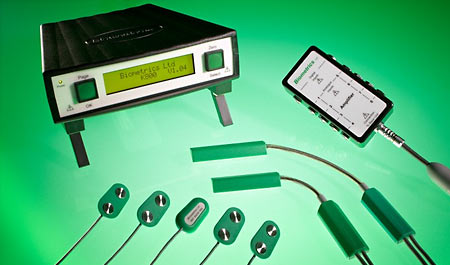
Biometrics K800 Amplifier
The K800 is a general purpose subject worn amplifier system allowing the user to collect analogue data from a wide range of sensors. The sensors are categorized into 2 groups:
- Differential output bridge type sensors including: Biometrics' Goniometers, Torsiometers, Hand Dynamometer, Pinchmeter
- Single ended high level sensors including: Biometrics' sEMG pre amplifier, NexGen Series 3 axis accelerometer
Examples of other differential type sensors include strain gauge based devices such as load cells and certain flow meters. A differential bridge type sensor may be connected providing it can be powered by +5 Vdc and the output is in the range of ± 12 mV. Examples of other single ended high-level sensors include potentiometers. A single ended high-level sensor may be connected providing it can be powered by +5 Vdc and the output is in the range of ± 3.5 V. For all 8 analogue channels the K800 recognizes automatically whether a differential bridge type sensor or single ended high level sensor is connected.
The K800 also has 5 digital channel inputs that are used for contact switches, event markers and synchronization with other systems.
Product Features
- Easy to use general purpose precision amplifier
- 8 analogue channels
- 5 digital channels
- +5V built in power supply
- Accepts all Biometrics Ltd sensors
- Accepts other sensors including load cells
- Real time display for all channels in engineering units
- RS422 digital data transfer from Subject Unit to Base Unit
The K800 Amplifier System provides a user friendly method for collecting signals from a variety of sensors in a format which may readily be connected to standard monitoring and recording instrumentation including proprietary A/D cards.
The K800 consists of 2 enclosures; a small lightweight Subject Unit and a larger table mounted Base Unit, both are microprocessor controlled. The signal between the 2 units is RS422. Although the K800 functions as a general purpose DC amplifier, the hardware is primarily digital circuitry, giving a design with the greatest accuracy, negligible drift, and the greatest immunity to noise.
The sensors connect to the small, lightweight Subject Unit with 8 instrumentation amplifiers and power supply responsible for energizing the sensors, converting all the inputs to digital signals and sampling the data. The signals are converted to digital signals as early as practical to minimize artifacts, and the data is transferred from the Subject Unit to the Base Unit via a RS422 data transfer cable 6 meters in length. The Base Unit converts the signals back to analogue for output to proprietary A/D systems. Alternatively, static readings may be displayed for each channel utilizing the LCD (liquid crystal display). The LCD and 2 button inputs act as the interface to configure the individual channels for the type of sensor attached. This enables any combination of sensors to be attached to any channels.
Event Marker IS3 (optional accessory)
A 1.8 metre cable with a suitable connector at one end to connect to the K800 Subject Unit, and a hand held switch on the other. This useful accessory allows time marks to be added to the data and enables the operator to highlight specific events during data collection.
Specifications
Mechanical
Dimensions: Subject Unit - 100 x 50 x 25mm, Base Unit - 180 x 170 x 48mm
Mass: Subject Unit - 150g, Base Unit - 550g
Electrical
Analogue channels: 8
Digital channels: 5
Subject Unit: microprocessor controlled
Base Unit: microprocessor controlled
Communication from Subject unit to Base unit: RS422
General analogue channels may be single ended high level or differential bridge type dependent on front end plug wiring configuration
Input voltage differential bridge mode: ± 12mV
Input voltage single ended high level mode: ± 3.5V
Output (full scale): Analogue +0.0 to +4.0 V
Analogue channel input impedance: 1M Ohm
Power supply per channel: + 5.0 V dc
Power supply per channel tolerance: ± 1 %
Accuracy: better than ± 0.5 % full scale
Maximum Common Mode: +3.5 V to -2.5 V
Bandwidth General: 5 Khz